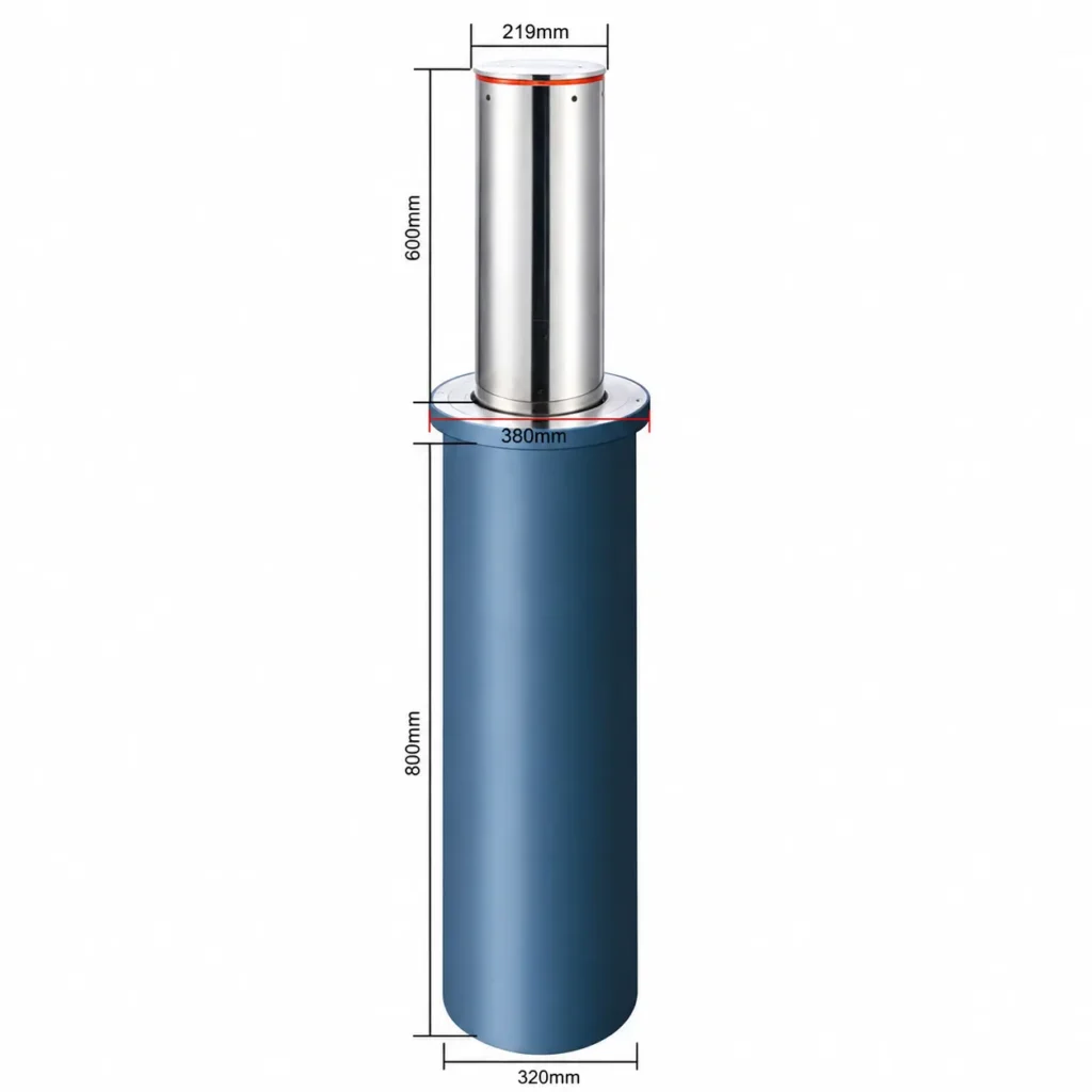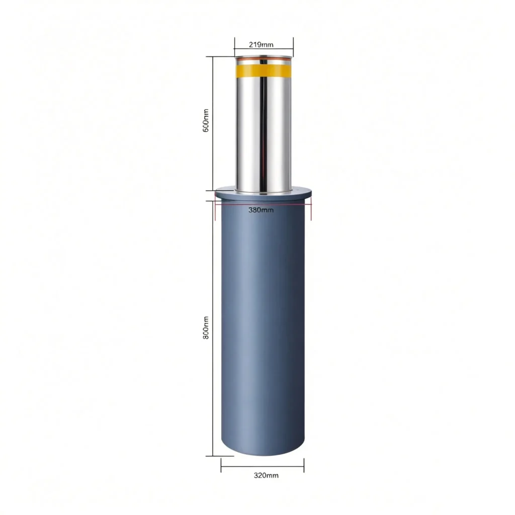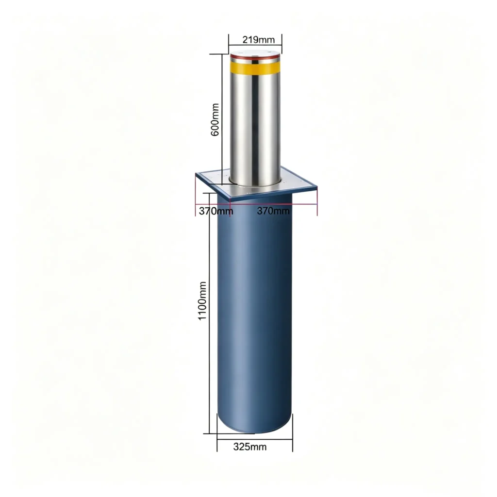
Correct wiring is essential for the safe and reliable operation of an automatic rising bollard system.
The motor, solenoid valve, LED warning light, and control box all use different electrical circuits. Incorrect connections may affect bollard raising and lowering, hydraulic pressure release, LED operation, or long-term system stability.
This guide explains the wiring configuration used in a typical 220V hydraulic rising bollard system, including cable selection, motor wiring, solenoid valve wiring, LED connections, control box power supply, waterproof cable joints, and emergency lowering during a power failure.
Important: The wire colors, terminal layout, and electrical specifications in this guide apply to the bollard system described here. Different bollard models or control systems may use different wiring configurations. Always follow the wiring diagram supplied with your equipment.
1. Rising Bollard Wiring Overview
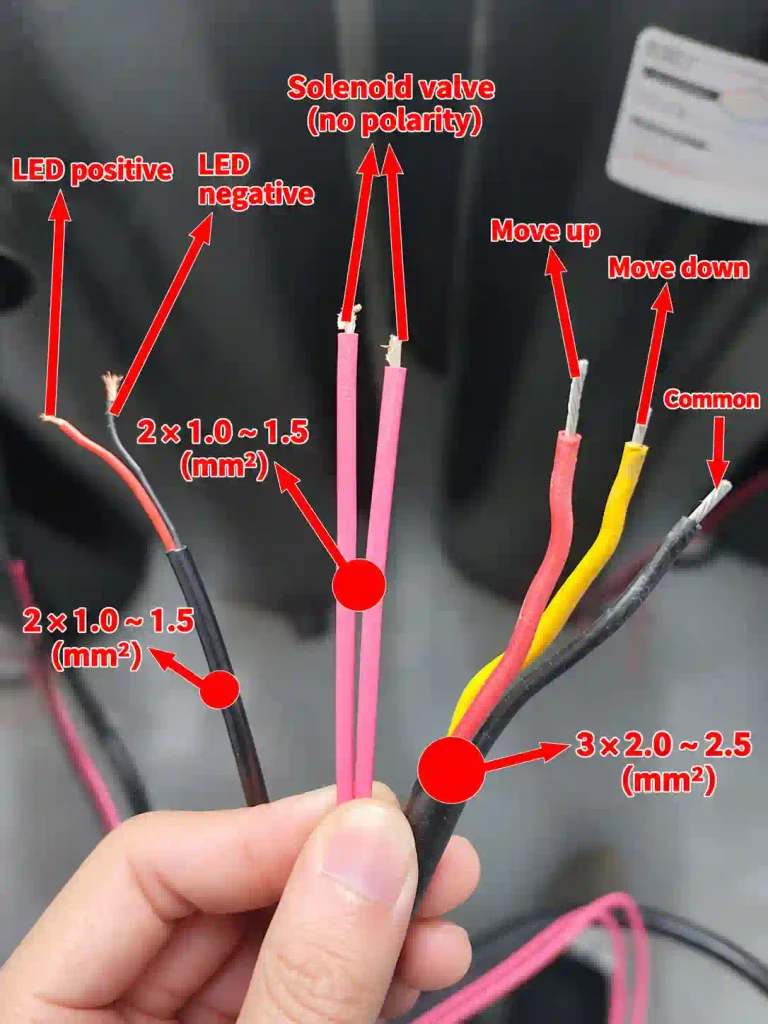
Each automatic rising bollard normally uses three main electrical circuits:
- Motor circuit
- Solenoid valve circuit
- LED warning light circuit
For the system described in this guide, the typical cable configuration is:
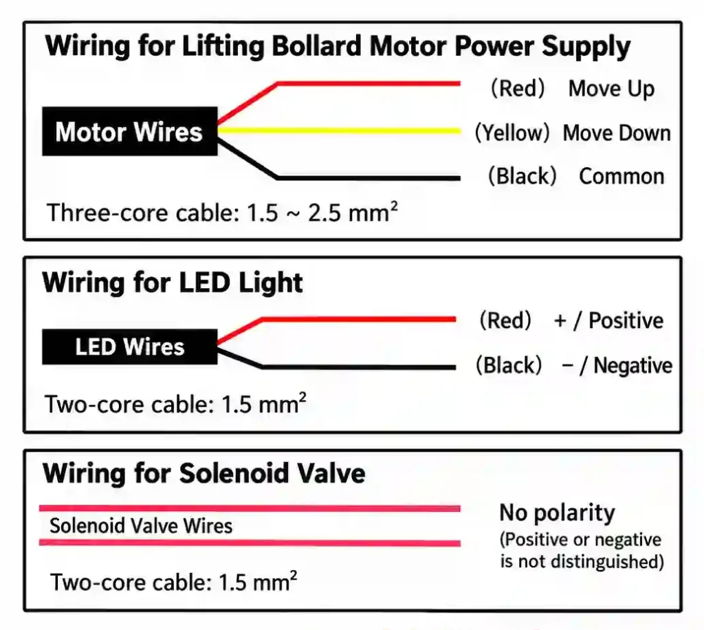
| Circuit | Cable | Voltage | Function |
|---|---|---|---|
| Motor | 3 × 2.0–2.5 mm² | AC 220V | Controls bollard raising and lowering |
| Solenoid Valve | 2 × 1.0–1.5 mm² | 12V | Releases hydraulic pressure for lowering |
| LED Warning Light | 2 × 1.0–1.5 mm² | 12V | Supplies power to the LED warning light |
In other words, each bollard normally requires:
1 × 3-core motor cable + 2 × 2-core low-voltage cables
The circuits should be routed and connected separately according to the control system design. Do not randomly combine or daisy-chain the circuits.
2. Automatic Bollard Motor Wiring
The motor used in this bollard system has three wires:
- Red — Raise
- Yellow — Lower
- Black — Common
These wires connect to the corresponding motor terminals inside the bollard control box.
Because the motor operates at AC 220V, always confirm the raise, lower, and common terminals before switching on the power.
For Multi-Bollard Installations
When several bollards are connected to the same control box, label each motor cable before installation.
For example:
- Bollard 1 Motor
- Bollard 2 Motor
- Bollard 3 Motor
- Bollard 4 Motor
Clear cable identification makes installation easier and greatly reduces mistakes during future inspection or maintenance.
3. Solenoid Valve Wiring
The solenoid valve is responsible for releasing hydraulic pressure when the bollard needs to lower.
For this system, the solenoid valve uses a:
2 × 1.0–1.5 mm² low-voltage cable
The two wires should be connected to the corresponding solenoid valve terminals inside the control box.
Each terminal pair normally corresponds to one bollard.
For example:
- Solenoid Terminal 1 → Bollard 1
- Solenoid Terminal 2 → Bollard 2
- Solenoid Terminal 3 → Bollard 3
For the system shown in this guide, the two solenoid valve wires do not require polarity identification.
The most important requirement is to make sure each bollard is connected to the correct terminal pair.
4. LED Warning Light Wiring
The LED warning light also uses a low-voltage circuit.
For this system, the recommended cable is:
2 × 1.0–1.5 mm²
Unlike the solenoid valve circuit, the LED circuit requires correct polarity.
The positive and negative wires must therefore be identified before connection.
Each bollard should be connected to its corresponding LED terminals inside the control box.
For multi-bollard installations, clearly label the LED cables before bringing them into the control cabinet.
Always use the terminal markings and wiring diagram supplied with the actual control box as the final reference.
5. Cable Length and Voltage Drop
Both the solenoid valve and LED warning light operate on 12V low-voltage power.
If the control box is installed too far away from the bollards, voltage drop along the cable may affect operation.
Possible problems include:
- Solenoid valve not operating correctly
- Hydraulic pressure not releasing normally
- Bollard unable to lower
- LED warning light becoming dim
- LED warning light failing to operate
For this system, the 12V solenoid valve and LED cable runs should preferably remain within approximately:
50 meters
If a longer installation distance is required, the cable size and electrical design should be reviewed before installation.
6. Control Box Power Supply
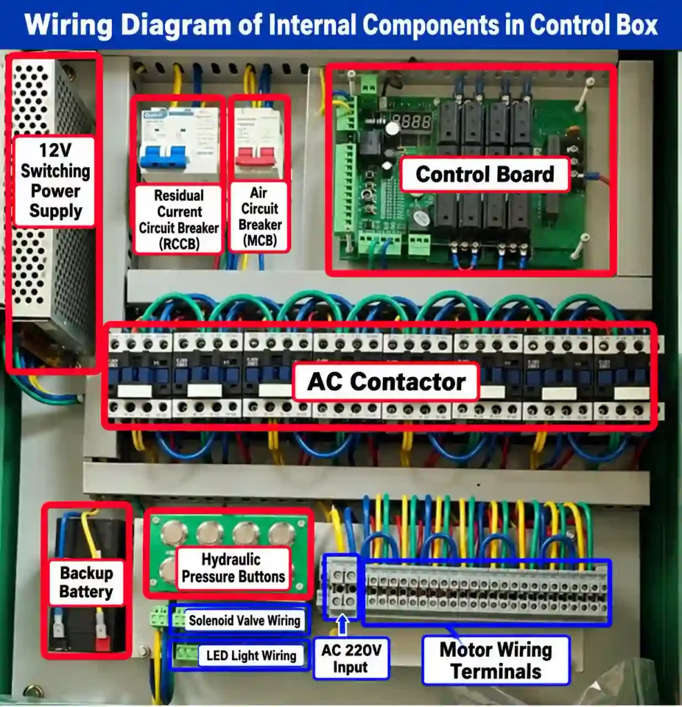
The control box is the main electrical control unit of the automatic bollard system.
For the control system used in this example, a:
2-core 6 mm² incoming power cable
is used for the main power supply.
The incoming cable connects to the main power terminals inside the control box.
Typical Electrical Data
Operating voltage per bollard: AC 220V
Approximate peak power per bollard: 600W
The incoming cable size should not be selected only by copying the example above.
For projects using four, six, eight, or more bollards, the required cable size and power supply should be determined according to the total system load, installation distance, and actual project design.
7. Label Every Cable Before Connecting the Control Box
Cable identification becomes especially important when several automatic bollards are installed together.
Each bollard normally has three separate circuits:
- Motor
- Solenoid valve
- LED light
A simple labeling system can prevent major wiring mistakes.
For example:
Bollard 1
- Bollard 1 Motor
- Bollard 1 Solenoid Valve
- Bollard 1 LED
Bollard 2
- Bollard 2 Motor
- Bollard 2 Solenoid Valve
- Bollard 2 LED
Continue the same labeling method for all remaining bollards.
This makes control box wiring, troubleshooting, and future maintenance much easier.
8. Waterproof Underground Cable Connections
Automatic bollards are installed outdoors and part of the wiring is normally located underground.
For this reason, waterproof treatment of cable joints is extremely important.
Poorly protected cable joints may lead to:
- Electrical leakage
- Circuit breaker tripping
- Short circuits
- Cable corrosion
- Electrical component damage
Recommended Waterproofing Procedure
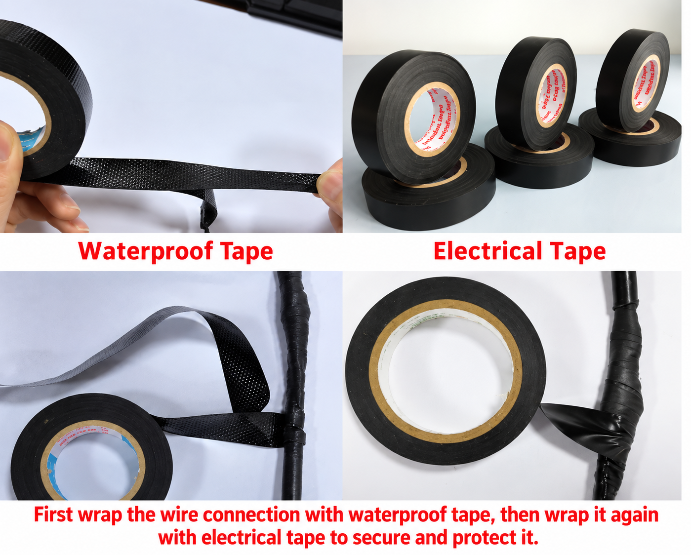
Step 1 — Connect the cables
Connect the site-installed cable to the corresponding original bollard cable.
Step 2 — Check the connection
Make sure each joint is secure and that no conductor is loose.
Step 3 — Insulate the joint
Cover the connection properly before applying the waterproof layer.
Step 4 — Apply waterproof tape
Stretch and tightly wrap waterproof self-fusing tape or suitable waterproof electrical tape around the entire cable joint.
Step 5 — Add an outer insulation layer
Apply standard electrical insulation tape over the waterproof layer for additional protection.
Step 6 — Return the cable joint to the storage box
Place the completed joint inside the bollard cable storage box and tighten the cable gland or connector.
Underground cable joints should not be left exposed.
Keeping them protected inside the cable storage box improves reliability and also makes future inspection easier.
9. Pre-Power Wiring Checklist
Do not switch on the system immediately after finishing the wiring.
Before powering the control box, check the following:
- Motor raise wire is connected correctly
- Motor lower wire is connected correctly
- Motor common wire is connected correctly
- Solenoid valve is connected to the correct terminal pair
- LED polarity is correct
- Each bollard cable is clearly identified
- All terminals are properly tightened
- No cables are mixed between different bollards
- Underground cable joints are properly insulated and waterproofed
After tightening the terminals, gently pull each wire to make sure the connection is secure.
Only after all connections have been checked should the main leakage protection switch be turned on for system testing.
10. Emergency Lowering During a Power Failure
This bollard control system includes a battery-related emergency lowering function.
If the mains power fails while the bollard is raised, the backup battery can supply power to the solenoid valve.
Once the solenoid valve is activated, hydraulic pressure is released and the bollard can lower.
This provides an emergency access solution when normal mains power is unavailable.
After power is restored, the battery can be recharged according to the equipment instructions.
For this system, a charging period of approximately:
3–5 hours
is recommended before switching off the related circuit breaker.
Automatic Rising Bollard Wiring FAQ
What cables are required for one automatic rising bollard?
For the system described in this guide, one bollard normally uses one 3-core motor cable and two 2-core low-voltage cables.
What voltage does the bollard motor use?
The motor in this system operates at AC 220V.
What voltage do the solenoid valve and LED light use?
Both operate on 12V low-voltage power in this system.
Does the solenoid valve have positive and negative polarity?
For the system described here, the solenoid valve wires do not require polarity identification.
Does the LED warning light require polarity?
Yes. The positive and negative LED connections must be identified correctly.
How far can the control box be installed from the bollards?
For this system, the 12V solenoid valve and LED cable runs should preferably be kept within approximately 50 meters. Longer distances may require a review of cable size and voltage drop.
Can several bollards share one control box?
Yes, depending on the control system configuration. Each bollard’s motor, solenoid valve, and LED cables should be clearly labeled and connected to the corresponding terminals.
Conclusion
Correct wiring is essential for the reliable operation of an automatic rising bollard system.
The key points are to correctly identify the motor, solenoid valve, and LED circuits; connect each bollard to the correct control box terminals; control voltage drop on low-voltage cable runs; and properly waterproof all underground cable joints.
For multi-bollard projects, clear cable labeling is equally important because it simplifies installation, testing, troubleshooting, and long-term maintenance.
Before powering on the system, always check every terminal and cable connection carefully and follow the wiring diagram supplied with the specific bollard and control box.