
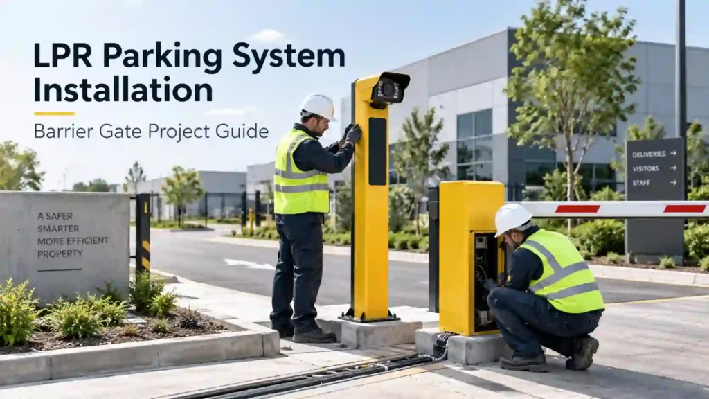
A successful LPR parking system installation requires the camera, access-control rules, barrier gate, vehicle detection devices, safety sensors, network, and site infrastructure to operate as one coordinated entrance system.
The installation involves much more than fixing a camera terminal and barrier cabinet to the ground. Equipment positioning, concrete foundations, protected cable routes, electrical connections, camera alignment, safety integration, and system commissioning all directly affect long-term reliability.
For contractors, system integrators, distributors, property managers, and project buyers, careful planning before installation can reduce civil-work changes, wiring errors, recognition problems, and unnecessary project costs.
Important: Foundation dimensions, supply voltage, cable specifications, terminal assignments, protective devices, camera settings, and safety requirements must follow the approved project drawings, selected equipment manual, and applicable local electrical and civil-work regulations.
What Is an LPR Parking System?
An LPR parking system is a vehicle access-control solution that automatically reads license plates and uses the recognition result to determine whether a vehicle should be allowed through an entrance or exit.
LPR means License Plate Recognition, while ANPR, or Automatic Number Plate Recognition, is another commonly used industry term for the same technology.
A typical LPR parking entrance may include:
- An LPR or ANPR camera or integrated recognition terminal
- An automatic barrier gate and boom arm
- Parking or access-control management software
- Network and power infrastructure
- Vehicle detection using loop detectors or radar
- Anti-fall or anti-crush safety devices
- Optional displays, intercoms, card readers, payment terminals, or traffic lights
The recognition unit normally communicates with the barrier controller through a control interface. Depending on the system architecture, this may use relay contacts, alarm input/output, serial communication, a dedicated controller, or network-based integration.
What Does a Typical LPR Parking System Installation Include?
A typical installation combines civil work, mechanical installation, electrical wiring, network configuration, and system commissioning.
The main field work generally includes:
- Preparing concrete foundations and underground conduit
- Positioning the LPR terminal and barrier gate
- Aligning both devices with the vehicle lane
- Drilling and installing mounting anchors
- Assembling the recognition unit
- Routing power, network, detector, and control cables
- Connecting wiring according to the equipment diagram
- Powering the equipment safely
- Configuring the camera and access-control logic
- Testing the complete vehicle-entry sequence
Several installation principles are especially important for B2B projects.
A stable foundation comes first. Outdoor cabinets should be mounted on suitable concrete foundations rather than placed directly on an unfinished road surface.
Equipment alignment must be coordinated. The recognition terminal, barrier arm, vehicle path, stop position, and safety detectors should be planned as one lane rather than as separate devices.
Cable routing should be included in the civil-work plan. Underground conduit and protected cable paths simplify maintenance and reduce the risk of exposed or damaged wiring.
The wiring diagram must be followed carefully. Power, network, vehicle detection, safety, and barrier-control terminals vary between brands and models.
Maintenance access should remain available. Installers need sufficient space to open covers, inspect terminal blocks, replace components, and service the equipment after commissioning.
What Should Be Confirmed Before Installation?
A site survey should be completed before concrete foundations are poured or pavement channels are cut.
Confirm:
- Lane dimensions
- Vehicle direction
- Vehicle turning path
- Camera recognition zone
- Barrier position
- Power supply
- Network connection
- Underground conduit
- Drainage
- Safety-device positions
- Maintenance clearance
- Environmental conditions
Early confirmation of these items can prevent expensive relocation or cable modifications after the equipment has already been installed.
Lane and Vehicle Conditions
Record the usable lane width, entrance and exit direction, turning radius, road slope, stop position, expected traffic volume, and typical vehicle types.
A layout designed mainly for passenger cars may not perform the same way when trucks, vans, buses, or vehicles with large turning radii use the entrance.
Photograph the vehicle approach and evaluate possible obstructions such as:
- Walls
- Columns
- Landscaping
- Signage
- Adjacent traffic lanes
- Strong sunlight
- Headlights
- Shadows
- Reflective surfaces
These factors help determine the appropriate camera position, recognition zone, detector arrangement, and barrier configuration.
Power, Network, and Conduit
Before installation, confirm the available power supply, grounding method, network connection, control-room location, and cable distance.
Underground conduit should preferably be planned before the concrete equipment pads are completed.
Power wiring and low-voltage signal or data wiring should be installed according to the equipment requirements and applicable electrical regulations. Many projects use separate pathways for power and communication cables to reduce interference and simplify future maintenance.
Cable entries should terminate within the cabinet footprint whenever possible.
Provide sufficient cable length for termination while avoiding:
- Excessive bending
- Exposed cable coils
- Unsupported wiring
- Unsealed outdoor connections
Outdoor cable entries should also include appropriate sealing, strain relief, and environmental protection.
Camera View and Lighting
The license plate recognition camera installation position must provide a clear view of the license plate inside the intended recognition zone.
Important factors include:
- Mounting height
- Horizontal angle
- Vertical angle
- Camera-to-vehicle distance
- Lens selection
- Vehicle speed
- Plate size in the image
- Ambient lighting
- Headlight exposure
- Vehicle turning angle
Camera alignment should not be approved using only one stationary vehicle under ideal daylight conditions.
Where possible, test representative vehicles under the conditions the entrance will actually experience, including daytime, nighttime, glare, shadow, headlights, and rain.
Safety and Maintenance Access
A barrier arm is a moving mechanical component and must be integrated with appropriate vehicle-detection and safety devices.
Depending on the project, the system may use:
- Inductive loop detectors
- Radar sensors
- Photocells
- Other vehicle-presence detection devices
The safety logic must be tested before the lane is released for normal operation.
The installation should also leave enough space to:
- Open equipment doors
- Remove covers
- Reach terminal blocks
- Inspect cables
- Replace electronic components
- Maintain the barrier mechanism
Where vehicle impact is possible, equipment islands, curbs, bollards, or other protective measures may also be required.
How to Install an LPR Parking System Step by Step
A professional LPR barrier gate installation can be divided into eight main stages.
1. Prepare the Foundation and Cable Route
Construct stable, level concrete mounting pads according to the approved equipment drawings and local ground conditions.
Before pouring the foundation, determine where the underground conduits will enter each cabinet.
Ideally, cables should rise inside the cabinet footprint rather than outside the enclosure.
For installations on existing pavement, mark the required cable path before cutting.
Check for:
- Existing underground utilities
- Drainage pipes
- Reinforcement
- Communication cables
- Other buried obstacles
If a pavement channel is required, route the cables through suitable protected conduit between the LPR equipment and barrier gate.
Foundation dimensions, anchor specifications, and curing requirements should follow the selected equipment drawings rather than generic dimensions.
2. Position and Align the Equipment
Place the LPR recognition terminal and barrier cabinet on their planned foundations before permanently tightening the anchors.
Check:
- Vehicle approach direction
- Barrier-arm orientation
- Recognition zone
- Lane clearance
- Cabinet-door clearance
- Maintenance space
- Relative equipment position
This is an important checkpoint.
Relocating the equipment after drilling, anchoring, or cable termination can create significant rework.
3. Mark, Drill, and Anchor the Cabinets
Mark the mounting-hole positions according to the cabinet base plate or approved mounting drawing.
Drill the holes to the required diameter and depth, clean the holes, and install the specified expansion anchors or other approved fixing system.
After placing the cabinet back into position, tighten the mounting nuts evenly.
The enclosure should remain:
- Vertical
- Stable
- Properly supported
- Free from twisting or deformation
Do not rely on anchor tightening to compensate for an uneven concrete surface.
Correct the foundation or bearing surface first.
A poorly secured cabinet can affect camera alignment, create vibration, and place unnecessary stress on electrical connections.
4. Assemble the LPR Recognition Unit
Install the recognition camera, display, or upper housing onto the corresponding mounting points.
Route internal cables through the intended channel before fully securing the upper assembly.
Avoid:
- Pinching cables
- Pulling connectors
- Sharp metal edges
- Unsupported cable weight
- Excessive cable bending
Final camera alignment should be completed during commissioning using a representative vehicle positioned inside the actual capture zone.
5. Route and Terminate Power, Data, and Control Cables
Power should be isolated before opening electrical terminal areas or making wiring connections.
Identify and label each conductor at both ends.
Connections should be completed according to the model-specific wiring diagram.
Typical functions may include:
- Equipment power
- Protective earth
- Network communication
- Vehicle-trigger input
- Barrier-open output
- Barrier status input
- Barrier-close control
- Anti-fall safety input
- Display connection
- Intercom connection
- Traffic-light interface
- Payment-system connection
The communication between the LPR controller and barrier gate may vary significantly between systems.
Common methods include:
- Dry-contact relay
- Alarm output
- Digital input/output
- Serial communication
- Dedicated access controller
- Network communication
Terminal names and voltage levels should never be assumed to be interchangeable between different manufacturers.
After connection, secure the cables and maintain appropriate bend radius.
Where cables pass through metal enclosures, use suitable glands, bushings, or other protective fittings.
Outdoor conduit openings should also be sealed against water, insects, and debris.
6. Close and Restore the Cable Route
Before sealing a pavement channel or underground route, inspect the installed cables.
Check:
- Cable continuity
- Cable labeling
- Insulation condition
- Conduit condition
- Connection direction
- Available service length
Recording the underground cable route with photographs and measurements can make future maintenance substantially easier.
The pavement should then be restored using a method appropriate for the surface type and traffic load.
Poorly sealed pavement channels may allow water to enter the conduit or deteriorate under repeated vehicle traffic.
7. Power Up the Equipment Safely
Inspect all electrical connections before energizing the system.
Confirm that:
- The available supply matches the equipment requirement
- Appropriate protection is installed
- Grounding is completed correctly
- No conductor strands are exposed
- No tools remain inside the cabinet
- No loose metal debris is present
- Cable terminals are secure
Initial power-up should be completed by appropriately qualified personnel following the approved electrical procedure.
Check each device individually before testing the complete entrance system.
8. Configure and Commission the Complete Lane
Physical installation is only part of an LPR parking system installation.
The complete system must also be configured and tested.
Typical commissioning tasks include:
- Adjusting the camera field of view
- Setting the plate-recognition region
- Configuring network parameters
- Synchronizing system time
- Creating access rules
- Configuring allowlists or blocklists
- Setting barrier-control outputs
- Configuring detector inputs
- Verifying safety logic
- Checking event records
Then test the entire vehicle process:
- A vehicle enters the detection zone.
- The recognition camera captures a usable plate image.
- The plate result is processed by the access-control system.
- The system determines whether access is authorized.
- The correct command is sent to the barrier controller.
- The barrier rises correctly.
- Safety detection prevents unsafe closing while the vehicle is underneath the arm.
- The barrier closes only after the lane is clear.
Additional scenarios should also be tested, including:
- Authorized vehicles
- Unauthorized vehicles
- Unreadable plates
- Different vehicle sizes
- Tailgating situations
- Manual override
- Network interruption
- Day and night operation
Before handover, document the final camera view, configuration settings, wiring schedule, network addresses, access rules, and commissioning results.
How Does the LPR Camera Control the Barrier Gate?
An LPR camera or controller reads the vehicle plate and checks it against the configured parking or access-control rule.
If access is permitted, the controller sends an opening command to the barrier gate.
A separate vehicle detector or safety sensor then helps determine whether the vehicle is still under the barrier and when the arm can safely close.
The exact control interface depends on the selected equipment.
A common system may use a dry-contact relay connected to the barrier controller’s opening input.
Other systems may use:
- Alarm input/output
- Serial communication
- A dedicated controller
- Network integration
For projects combining equipment from different manufacturers, interface compatibility should be confirmed before ordering.
Common Installation Problems and How to Avoid Them
Why Does the Camera Read Plates Inconsistently?
Check:
- Camera angle
- Plate size within the image
- Focus
- Exposure
- Lighting
- Vehicle speed
- Recognition zone
- Vehicle turning direction
Software settings cannot fully compensate for a plate image that is too small, blurred, overexposed, poorly focused, or physically obstructed.
Why Doesn’t the Barrier Open After Valid Recognition?
Check:
- Access-control rule
- Barrier-output configuration
- Terminal assignment
- Relay mode
- Common connection
- Pulse duration
- Barrier input settings
Testing the barrier input independently can help determine whether the problem originates from the barrier controller, wiring, or recognition system.
Why Does the Barrier Close Unsafely?
Stop normal operation and inspect the vehicle-detection and anti-fall system.
Check the:
- Detector location
- Wiring
- Logic state
- Sensitivity
- Controller configuration
- Barrier closing behavior
Safety operation should always be verified using actual vehicles before the entrance is opened for routine use.
Why Does the Cabinet Move or Vibrate?
Inspect:
- Concrete condition
- Anchor specification
- Mounting holes
- Fastener tightness
- Cabinet verticality
- Foundation level
- Possible vehicle impact
Movement can gradually change the camera recognition angle and place stress on internal cable connections.
Why Is Water Entering the Cabinet or Conduit?
Check:
- Cable glands
- Conduit slope
- Cable-entry seals
- Cabinet base
- Drainage
- Covers
- Damaged seals
Underground conduit should not become a channel that directs rainwater into electrical equipment.
Why Is Communication Unstable?
Check:
- Cable type
- Cable distance
- Connector termination
- Network configuration
- IP address conflicts
- Grounding
- Power quality
- Electromagnetic interference
- Cable separation
Clearly labeling every cable at both ends can greatly simplify troubleshooting.
What Should B2B Buyers Provide Before Quotation?
For an accurate LPR parking system quotation, buyers should provide enough project information for the supplier or system integrator to understand the entrance layout and required operating logic.
A useful inquiry package includes:
- Site drawings or a marked layout
- Entrance and exit photos
- Lane width
- Road slope
- Vehicle turning direction
- Available equipment-island dimensions
- Number of entrance and exit lanes
- Passenger-car, truck, or mixed-traffic requirements
- Required barrier clear opening
- Existing power supply
- Network availability
- Distance to the control room
- Required access-control workflow
- Existing barrier-gate model if integration is required
- Existing controller interface
- Required vehicle detector
- Required anti-fall safety device
- Intercom requirements
- Display requirements
- Traffic-light requirements
- Environmental conditions
Buyers should also explain how the entrance is expected to operate.
Common access workflows include:
- Allowlist vehicle access
- Visitor access
- Employee parking
- Residential parking
- Ticketless parking
- Paid parking
- Operator-assisted entry
Providing this information early allows the supplier to distinguish between standard equipment, optional accessories, software requirements, and project-specific engineering.
What Affects LPR Parking System Cost?
The cost of an LPR parking system depends on the complete project scope rather than only the camera or barrier price.
Major cost factors include:
- Number of lanes
- Camera configuration
- Barrier-gate type
- Boom-arm configuration
- Vehicle detectors
- Safety sensors
- Civil work
- Cable distance
- Network infrastructure
- Parking software
- Third-party integration
- Installation
- Commissioning
- Freight
- Local labor
- Taxes
- Site restoration
When comparing quotations, buyers should ask suppliers to separate:
- Core equipment
- Optional accessories
- Software licenses
- Service fees
- Civil work
- Electrical work
- Installation
- Commissioning
- Training
- Documentation
- After-sales support
- Freight
- Duties
- Local compliance work
This makes it easier to compare equivalent project scopes rather than comparing a basic equipment price with a complete installed solution.
What Maintenance Is Required After Installation?
An LPR parking entrance should be inspected regularly according to its traffic volume and operating environment.
Routine maintenance may include:
- Cleaning the camera lens or protective window
- Checking camera alignment
- Inspecting concrete anchors
- Checking cabinet seals
- Inspecting cable glands
- Checking underground cable entries
- Testing vehicle detectors
- Testing anti-fall safety functions
- Inspecting barrier movement
- Reviewing system event logs
- Backing up configuration information
Additional inspection is recommended after:
- Vehicle impact
- Severe weather
- Pavement repair
- Electrical work
- Network changes
- Equipment relocation
Approved wiring diagrams, configuration records, network information, and commissioning documentation should be retained for future maintenance teams.
Frequently Asked Questions
Can an LPR Parking System Be Installed Outdoors?
Yes, provided that the selected equipment and installation method are suitable for the site’s environmental conditions.
Before purchasing, confirm the required enclosure protection, corrosion resistance, operating temperature, drainage, cable sealing, electrical protection, and foundation requirements for the selected model.
Do not assume environmental ratings without checking the manufacturer’s technical documentation.
How Should an LPR Camera Be Positioned at a Barrier Gate?
Position the camera where the license plate remains clearly visible within the intended recognition zone before the vehicle reaches the barrier.
The correct mounting height, angle, distance, and lens depend on:
- Lane geometry
- Vehicle path
- Vehicle speed
- Plate format
- Camera model
- Lighting conditions
Final positioning should be validated using representative vehicles and the manufacturer’s live-view or installation tools.
What Cables Are Needed Between the LPR Unit and Barrier Gate?
The cable requirements depend on the system architecture.
A project may require:
- Power cable
- Network cable
- Barrier-control cable
- Detector cable
- Safety-device cable
- Optional display or intercom wiring
Some systems use relay contacts, while others use dedicated controllers or communication interfaces.
Always follow the selected model’s wiring diagram.
Does an LPR Barrier Gate Need a Loop Detector or Radar?
Most vehicle-access projects require some form of vehicle detection and anti-fall safety logic, but the appropriate device depends on the entrance design.
Possible solutions include:
- Inductive loop detectors
- Radar sensors
- Photocells
- Combined detection systems
The system designer should define separately how the vehicle triggers recognition and how the barrier is prevented from lowering onto a vehicle.
What Foundation Is Required for an LPR Parking Terminal?
Use a stable, level concrete foundation designed for the selected cabinet, anchoring system, underground conduit, soil conditions, drainage, and site traffic.
There is no universal foundation size suitable for every LPR terminal or barrier gate.
Foundation dimensions and anchor requirements should come from the selected equipment drawing and approved project design.
How Do You Test the System After Installation?
Test the entire vehicle sequence rather than checking only whether the camera can read a license plate.
Verify:
- Vehicle detection
- Plate capture
- Recognition result
- Access-rule processing
- Barrier opening
- Safety hold
- Vehicle passage
- Barrier closing
Repeat the test using authorized and unauthorized plates, different vehicle types, varying lighting conditions, manual controls, and agreed exception procedures.
Can an LPR System Work With an Existing Barrier Gate?
Often yes, provided that the existing barrier controller offers a compatible control input and the required safety functions can be integrated correctly.
Before purchasing the LPR equipment, provide the supplier with:
- Barrier brand and model
- Wiring diagram
- Controller information
- Input type
- Supply information
- Existing detectors
- Current operating logic
Do not assume that similar terminal names mean that two different systems are electrically compatible.
What Causes Poor License Plate Recognition After Installation?
Common causes include:
- Incorrect camera angle
- Plate image that is too small
- Motion blur
- Poor focus
- Glare
- Headlight overexposure
- Dirty camera optics
- Vehicle obstruction
- Incorrect recognition zone
Recognition performance and barrier-control problems should be diagnosed separately. A camera may correctly recognize a plate even when network or access-rule problems prevent the barrier from opening.
Conclusion
A reliable LPR parking system installation begins with coordinated site planning and ends with verified vehicle-lane operation.
The essential installation process includes preparing the foundation, positioning and anchoring the equipment, assembling the recognition unit, routing and terminating cables, supplying power, configuring the camera, integrating safety devices, and commissioning the complete entrance.
For B2B projects, equipment selection should also be matched to the lane dimensions, vehicle types, environmental conditions, access rules, existing systems, and local installation requirements.
Thorough preparation reduces installation rework, improves maintainability, and gives suppliers and integrators the information they need to design a complete vehicle-access solution instead of simply combining individual devices.
Need an LPR Parking System for Your Project?
If you are planning a new parking entrance or need to integrate license plate recognition with an existing barrier gate, send us:
- Lane width
- Entrance photos
- Vehicle types
- Barrier opening width
- Power conditions
- Network conditions
- Required access workflow
- Existing equipment information
- Required vehicle-detection and safety devices
We can review the project requirements and help determine a suitable LPR, barrier gate, control-interface, and accessory configuration for quotation.